Feeder Optimization sounds like a setup task. It is really a profit-control task.
In SMT production, a misplaced high-usage reel can punish a line thousands of times per shift. The loss may be only 0.05 seconds per pickup, but repeated across resistors, capacitors, LEDs, QFNs, BGAs, and connectors, it becomes measurable machine cycle time. I have seen teams chase new placement machines while ignoring the cheaper problem sitting in front of them: feeder positioning that was inherited, not engineered.
Why Feeder Optimization Decides Real Machine Cycle Time
A pick-and-place machine does not run at brochure speed when the head is forced into poor travel paths, repeated nozzle changes, unstable pickup points, or inefficient feeder-side allocation. That is the first hard truth. The second is worse: many factories normalize this loss because the machine still appears to be “running.”
But running is not the same as producing efficiently.
Feeder positioning controls how far the placement head travels between pickup and placement, how often it changes nozzles, how well it can gang-pick, and how frequently operators intervene. For Машины для подбора и размещения оборудования, the feeder map is not a side file. It is a motion strategy.
The best feeder optimization techniques start with usage frequency, not convenience. High-pick-count parts such as 0402 resistors, 0603 capacitors, 10 kΩ pull-ups, 100 nF decoupling capacitors, LEDs, and repeated SOT-23 packages deserve premium feeder locations. Rare parts do not.
Simple rule. Often ignored.
What The Data Says About Feeder Positioning
The academic literature backs what experienced line engineers already know: feeder assignment, nozzle assignment, and component sequencing are tied together. A 2024 study in Engineering Proceedings proposed a simulation-based hierarchical heuristic for optimizing nozzle assignment, feeder assignment, and component sequencing in a spin-head gantry surface mounter, describing the combined problem as NP-hard rather than a simple slotting exercise. Read the SMT optimization study. (MDPI)
That matters because a feeder layout can look efficient while quietly increasing nozzle changes. Reducing X/Y travel is useful; reducing travel while creating extra nozzle swaps is fake optimization.
Cost pressure makes the mistake more expensive. IPC’s December 2024 electronics manufacturing sentiment data reported that 53% of electronics manufacturers were experiencing rising labor costs, while 45% reported rising material costs. In that environment, wasted placement motion is not a technical annoyance. It is margin leakage. See IPC’s December 2024 electronics sentiment data. (Электронная почта.ipc.org)
Automation pressure is rising too. Reuters reported in November 2024 that South Korea led global robot density with 1,012 robots per 10,000 employees, while China reached 470 and Germany stood at 429, based on International Federation of Robotics data. Read Reuters’ report on industrial robot density. (Reuters)
So the question becomes uncomfortable: if competitors are automating faster, can a factory still afford sloppy feeder setup optimization?
How To Optimize Feeder Positioning Without Fooling Yourself
Start with the machine log, not the operator memory. Export the placement file, rank every component by placement count, then group parts by package size, tape width, nozzle type, feeder type, and board location. This is where the real feeder map begins.
I would divide the component set into four groups:
High-frequency parts: 0402, 0603, 0805, LEDs, SOT-23, common capacitors, common resistors.
Nozzle-sensitive parts: QFN, BGA, SOIC, connectors, shields, odd-form components.
Changeover-sensitive parts: components shared across product families or recurring SKUs.
Risk-sensitive parts: parts with pickup errors, peel issues, vision rejects, or feeder-history problems.
For Устройство подачи SMT planning, high-frequency parts should generally sit near efficient pickup zones, but not at the expense of nozzle logic. If two components use the same nozzle family and appear repeatedly across the board, grouping them intelligently may reduce both travel and tool-change waste.
This is where many teams go wrong. They optimize feeder distance only. Then the machine loses time in nozzle exchange, camera handling, or pickup instability.
For смешанные линии SMT, feeder optimization must also protect changeover time. The fastest layout for one PCB may be the wrong layout for a family of products. Shared feeders, fixed common banks, barcode verification, and offline feeder cart preparation often matter more than shaving a tiny amount from a single board cycle.
For Прототипы и мелкосерийные линии SMT, I would be even more cautious. Setup accuracy, traceability, and fast verification can beat pure CPH. In high-mix production, a wrong reel costs more than a slightly longer travel path.
Feeder Setup Optimization Table
| Optimization Lever | What To Check | Expected Impact On Machine Cycle Time | Common Failure Mode | Best Fit |
|---|---|---|---|---|
| High-use feeder clustering | Top 20% components by pick count | Высокий | Placing feeders by BOM order instead of usage | High-volume PCBAs, LED boards, consumer electronics |
| Nozzle-aware grouping | Nozzle type, package size, pickup height | Высокий | Reducing travel but increasing nozzle swaps | Yamaha, Panasonic, Fuji, Juki, Hanwha SMT lines |
| Shared feeder banks | Components repeated across multiple SKUs | От среднего до высокого | Optimizing one job while damaging changeover time | Mixed SMT lines and family builds |
| Board-zone alignment | Component location by PCB area | Средний | Ignoring whether parts are mostly left, right, front, or rear of panel | Large panels and automotive PCBAs |
| Feeder health control | Peelers, sprockets, springs, calibration, tape tension | Средний | Blaming software for mechanical pickup faults | Aging feeder fleets |
| Offline setup verification | Reel ID, feeder ID, slot number, program match | High for uptime | Trusting manual setup without barcode checks | High-mix and low-volume production |
| Duplicate high-volume feeders | Repeated passives or LEDs | От среднего до высокого | Duplicating the wrong parts | High-speed mass production lines |
This table is deliberately practical. A mathematically elegant layout that ignores feeder condition is not optimized. It is fragile.
Common Mistakes That Kill Industrial Automation Efficiency
The first mistake is treating automated feeder systems as a substitute for engineering judgment. Smart carts, barcode systems, MES links, and feeder IDs can reduce human error, but they cannot fix a weak feeder strategy by themselves.
NIST’s manufacturing guidance states that robotics and automation can reduce variation and task time when applied correctly. That is the useful phrase: when applied correctly. Automation standardizes the process you give it, whether that process is good or bad. See NIST’s Industry 4.0 manufacturing guidance. (NIST)
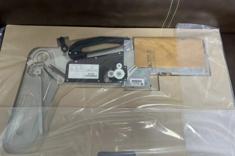
The second mistake is ignoring feeder wear. Worn sprockets, damaged covers, unstable peelers, loose feeder latches, and poor tape tension can erase the gains from a good software optimization. For that reason, запасные части и принадлежности belong inside the feeder optimization discussion, not after it.
The third mistake is over-optimizing one job. In высокоскоростные линии массового производства, aggressive feeder placement, duplicate reels, and tight nozzle planning make sense. In high-mix environments, a slightly slower per-board cycle may be better if it reduces changeover errors and stabilizes product-family setup.
The fourth mistake is trusting the default optimizer without checking real output. I do not care how good the software looks. Compare the proposed feeder map against actual cycle time, mis-pick rate, nozzle changes, feeder stops, and operator intervention. The line log is the witness.
Вопросы и ответы
What is feeder optimization in SMT assembly? Feeder optimization in SMT assembly is the process of assigning component feeders to machine slots so the placement head travels less, changes nozzles less often, picks parts more reliably, and completes each PCB faster while maintaining setup accuracy, traceability, and changeover control across real production conditions.
In practice, it combines feeder positioning, nozzle planning, component sequencing, feeder health control, and operator verification. It is not just “put the common parts closer.”
How do I optimize feeder positioning for machine cycle time reduction? To optimize feeder positioning for machine cycle time reduction, rank components by placement frequency, group compatible nozzle families, place high-use reels in efficient pickup zones, account for board geography, preserve shared feeders across product families, and validate every change against actual machine logs instead of theoretical CPH alone.
The best first move is a controlled audit. Change one feeder strategy, measure the result, then continue. If everything changes at once, nobody knows what worked.
What are the best feeder optimization techniques for automated feeder systems? The best feeder optimization techniques for automated feeder systems include barcode-verified slot setup, fixed common feeder banks, nozzle-aware sequencing, duplicate feeders for ultra-high-volume parts, offline cart preparation, feeder condition tracking, and routine comparison of planned cycle time against real pickup and placement performance.
Automation is strongest when it prevents wrong-reel loading, shortens setup verification, and gives engineers clean data. It is weakest when teams expect software to compensate for poor feeder discipline.
Can feeder setup optimization reduce cycle time without buying a new machine? Feeder setup optimization can reduce cycle time without buying a new machine when the current loss comes from excessive head travel, poor nozzle grouping, unstable pickup behavior, weak sequencing, bad feeder condition, or avoidable changeover work rather than from the machine’s mechanical speed limit.
That is why feeder optimization should happen before a capital-equipment decision. A faster machine can help, but it will not automatically fix poor setup logic.
Why does feeder positioning affect industrial automation efficiency? Feeder positioning affects industrial automation efficiency because every unnecessary head movement, nozzle exchange, feeder stop, setup correction, and pickup instability is repeated across hundreds or thousands of placements, converting small motion losses into measurable downtime, labor waste, lower throughput, and weaker schedule reliability.
In a competitive SMT plant, those seconds are not abstract. They decide whether the line meets takt time or quietly misses the plan all day.
Turn Feeder Data Into A Faster SMT Line
Reducing machine cycle time starts with a feeder map that reflects the product, the machine, the nozzle set, and the operator workflow. Not last year’s layout. Not a default program. Not whatever fit on the feeder cart at 2 a.m.
For factories planning a full line review, feeder optimization should be tied to Решения для линий SMT под ключ so placement speed, printer output, reflow capacity, inspection flow, conveyors, spares, and changeover logic are evaluated together.
The best next step is simple: pull the feeder table, placement count report, nozzle-change data, and downtime log. If the numbers show avoidable movement or setup waste, use the контактная страница to start a line-specific review. Bring the ugly data first. That is usually where the savings are.